
Replacing LED modules is a common maintenance requirement in commercial display projects. Whether due to module failure, the product is no longer made, or a decline in display quality, choosing the right replacement solution can help you reduce costs and minimise downtime.
Common Signs That an LED Module Needs Replacement

Dead Pixels or Pixel Clusters
If you notice persistent black pixels on a solid-colour test screen, and their number is increasing rapidly within a short period or has already formed dense clusters, this is not the result of isolated LED failures but rather indicates a systemic defect in the module’s internal drive circuitry or the LED batch. A small number of isolated dead pixels can be addressed later, but once large patches of dead pixels appear, continued use will accelerate degradation of surrounding pixels and severely impair the display’s performance; you should arrange for a replacement immediately.
Abnormal Colors
If the module displays fixed colour spots or colour casts that do not change with the content when showing low-brightness greyscale or solid-colour images, you should first check the ribbon cables and receiver card to rule out signal transmission faults. If the colour discrepancy persists, the cause lies in inconsistent light decay among LEDs from different batches within the module or a faulty driver IC. For applications in environments with stringent colour-consistency requirements, such as broadcast studios and exhibition halls, these modules cannot be effectively corrected through per-pixel calibration; we recommend replacing the entire batch.
Dark Areas on the Screen
When displaying a bright white image, if certain areas appear noticeably dimmer than their surroundings, forming mosaic-like dark patches, this is usually caused by excessive light decay in the LEDs within that area or a decline in the efficiency of the power supply circuit. The core issue with this type of fault is that replacing a single module results in the new module being significantly brighter than the surrounding older modules, creating a noticeable ‘patch effect’. If the display panel is in the middle to late stages of its service life, we recommend adopting a strategy of batch replacement by zone to maintain overall display uniformity.
Flickering Modules
If the module exhibits intermittent flickering that is not inherent to the scan lines, you should first check the supply voltage and ensure that all physical connections are secure; this is the most cost-effective troubleshooting step. If the above checks prove ineffective, the issue is likely to be a faulty driver chip within the module itself or a poor connection in the internal PCB circuitry. Such modules are in an unstable condition and may go completely black at any moment during critical display operations; as they are of very little value to repair, we recommend replacing them immediately to prevent operational incidents.
Physical Damage
Damage to a module caused by impact or compression—such as a cracked cover, detached LEDs or a broken copper trace on the PCB—can be clearly identified even when the module is not powered. Physical damage not only compromises the panel’s flatness and protective sealing, but the exposed circuitry also poses a short-circuit risk, potentially affecting other modules on the same power circuit. Such faults are beyond repair; you must immediately disconnect the power supply and replace the module with one of the same specification, whilst ensuring that adjacent modules are checked for any hidden damage.
Water Ingress Damage
Even if the exterior of the module appears dry, if any traces of water damage—such as mould spots or green rust—are observed on the PCB, solder joints or lamp pins, this should be professionally assessed as water ingress damage. Your primary rule is to strictly avoid attempting to power on the unit before it has been thoroughly cleaned and dried; otherwise, there is a very high probability that the entire power supply and receiver card circuitry will be instantly destroyed. Once water damage has been confirmed, severely water-damaged modules are usually replaced rather than repaired. At the same time, you must immediately trace the source of the leak and seal the leak point in the display panel; otherwise, the new module will face the same risk.
LED Module Repair vs Replacement
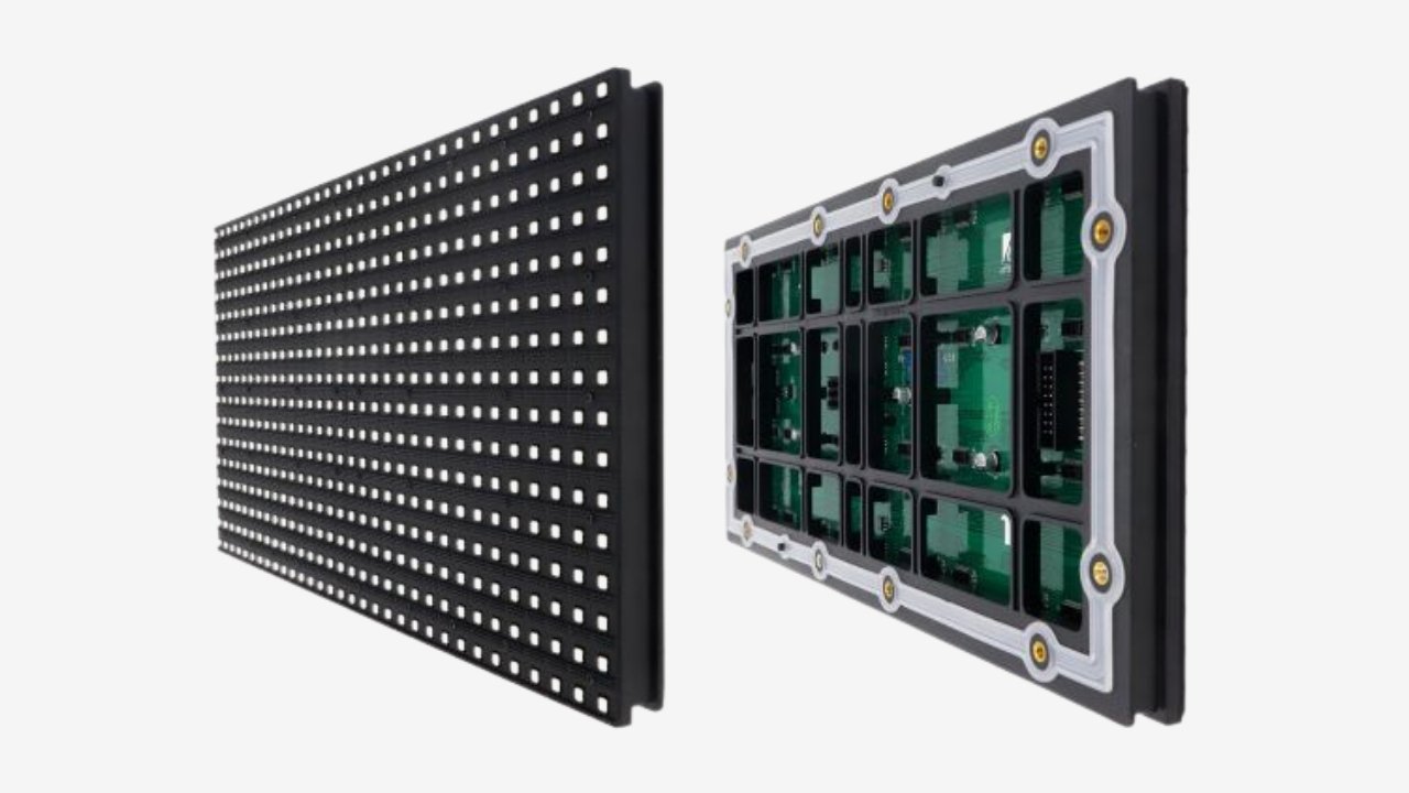
| Factor | LED Module Repair | LED Module Replacement |
| Cost | Lower initially | Higher initially |
| Downtime | Longer | Shorter |
| Reliability | Less predictable | More reliable |
| Lifespan | Limited extension | Longer service life |
| Display Quality | May vary | More consistent |
| Best For | Minor faults | Severe damage or ageing of modules |
How to Identify the Correct LED Replacement Module?

Pixel Pitch
Pixel pitch is the physical distance between the centres of adjacent pixels, measured in millimetres, and is the primary parameter for identifying modules. If verifying without documentation, simply use a calliper to measure the horizontal distance from the centre of one LED to the centre of the adjacent LED; the measured value is the pixel pitch. For example, if the measurement is 3 mm, a P3 module is required. You must ensure a perfect match, as even a deviation of 0.5 mm—such as between P2.5 and P3—will prevent the module from fitting into the cabinet mounting frame and result in irreparable pixel misalignment.
Module Sizes
The module dimensions refer to the overall physical width and height of the module, which are strictly dictated by the mechanical structure of the existing enclosure and constitute non-negotiable constraints. You must use a calliper to accurately measure the actual length and width of the module’s outer frame; do not rely on nominal values. Replacement modules must match these dimensions to the millimetre, as the mounting holes, magnetic studs and locating pins on the enclosure are fixed. Even a deviation of just a few millimetres will prevent the module from being physically installed, leaving you with no option but to return the item and purchase a new one, resulting in delays to the project schedule.
Scan Rate
The scan rate defines the number of rows that are illuminated simultaneously during a refresh cycle; it is embedded in the module’s PCB driver design, with common values being 1/8, 1/16 and 1/32 scan. If the scan count of a replacement module differs from the existing configuration, inconsistencies in brightness and refresh performance will occur, and the screen will display noticeable bright and dark stripes. You must confirm two key points before purchasing: firstly, that the scan count of the replacement module matches the existing one; and secondly, that the receiver card’s configuration profile supports this scan count. A mismatch in either of these will result in the display failing to function correctly.
HUB Interface
The HUB interface is the module’s data input port; its pin configuration is the aspect most easily overlooked yet most frequently responsible for replacement failures. Even if two modules use header sockets that appear identical, the arrangement of data channels, clock lines and latch signals on each pin may vary significantly depending on the manufacturer or even the production batch. You must compare the pinout diagram of the existing module’s HUB with that of the replacement unit pin by pin to ensure they are identical. If this step is overlooked, the module will display garbled characters or a completely black screen upon power-up.
LED Package Type
The LED package determines the physical dimensions, mounting structure and lens characteristics of each light-emitting unit on the module, and has a direct bearing on visual consistency and maintainability. When replacing LEDs, you must select a package with specifications that are identical to those of the existing module: the dimensions, mounting design and lens curvature must all be consistent. If different packages are mixed, for example, replacing an original SMD2121 package with SMD1921, the viewing angles, luminance curves and colour rendering performance of the two will be entirely different. This will result in a patchwork effect on the screen that cannot be eliminated through calibration, severely affecting display quality.
FAQ

How Many Spare LED Modules Should I Keep for Future Maintenance?
We recommend that you keep a stock of spare modules equivalent to 5% to 10% of the total number of modules in the display. For indoor LED displays, 5% serves as a baseline; for outdoor LED displays, where failure rates are higher due to environmental stresses, this should be increased to 10%. If the display is installed in critical environments where downtime is not tolerated—such as transport hubs or broadcast studios—or if the modules in that batch have been discontinued, you may increase the proportion of spares to 15%.
Can Replacement LED Modules Be Used with Existing Receiving Cards?
Yes, but only if the scan lines, data interface definitions and pixel mapping of the replacement module are the same as those in the existing receiver card’s configuration file. You will need to load the original receiver card’s configuration file or request the matching firmware from the manufacturer. If the interface pin definitions differ, the display may show garbled characters or a black screen, even if the physical connection is successful.
Is It Possible to Replace Only Part of a Cabinet Instead of the Entire Module?
No. The module is the smallest replaceable unit for maintenance. If the fault affects only some of the LEDs on the module, you will still need to replace the entire module. It is not possible to replace individual sections inside the housing, as the LEDs are directly soldered to the module’s PCB and the design does not allow for individual replacement, either mechanically or electrically.
How Long Do Replacement LED Modules Typically Last?
The half-life of a standard LED module is typically between 50,000 and 100,000 hours. This means that under normal operating conditions, it will take approximately 5 to 10 years for the brightness to drop to half its initial value. However, the actual lifespan is highly dependent on your operating environment and settings: poor heat dissipation or prolonged operation at high brightness levels will accelerate light decay, whilst proper maintenance can extend the lifespan to its theoretical maximum.
Are Replacement LED Modules Available for Displays That Are More Than Five Years Old?
Obtaining them may be difficult, but it is not impossible. As most modules from five years ago are no longer in production, you should first contact the original manufacturer to check if they have any remaining stock. If they have run out, you can turn to specialist third-party markets to look for stock items, or use second-hand modules salvaged from dismantled devices. Please note that due to natural ageing, the brightness and colour of older modules may differ from the current condition of your screen.
What Causes Frequent LED Module Failures in Outdoor Displays?
The primary cause is the sulphidation or short-circuit corrosion of the LEDs due to moisture ingress, which is usually caused by the ageing of the sealant or a failure in the enclosure’s protection. The second cause is inadequate heat dissipation; prolonged operation of the module at full load under high temperatures accelerates component failure. Finally, there is a power supply surging; an unstable mains supply, if not protected by effective surge protection, will repeatedly subject the driver ICs and LEDs to voltage spikes, resulting in widespread damage.
Final Thoughts

LED module replacement is a cost-effective way to restore display performance and minimise downtime. Whether you need compatible replacements for existing screens or solutions for discontinued models, our team can help. Contact us today for expert advice, fast support, and a tailored quotation for your project.

